Tuesday, April 9, 2019

TeleVideo Systems Part IV - TS-801

TeleVideo TS-801 "System I"


The TeleVideo TS-801 was TeleVideo's first entry into the single-user CP/M computer market. It was also usable as a client system off of one of their distributed systems, which were centered around one of the TS-806 or TS-816 "Service Processor" systems.

The system is not expandable but arrives as a fairly well-configured system.  It was released in 1981 and listed for $3295 with a 4MHz Z-80, 64KB of ram, two floppy drives, a couple of serial ports, and a Centronics-compatible parallel printer interface.


Outside appearances


The TS-801 has a pair of double-sided/double-density Tandon TM100-2A floppy drives with up to 360KB of storage each, plus a red reset button on the front.  On the back, there's a DB-25 terminal port for the console terminal, a DB-25 serial printer port, and a 36-pin Centronics parallel port, along with a DA-15 RS-422 port to connect to a Service Processor for use in a distributed system.


Due to how the machine is set up, you can either use the RS-422 port or the serial printer port.  To switch between the two, there are a set of jumpers on the motherboard that need to be cut and re-soldered differently.  This is probably the worst way I could think of implementing this.  However, I'm sure that it was expected that you would only change this at most once when the system was initially installed.


Disassembly

The inside of the TS-801 is fairly simple and designed to be serviceable. The major chips are socketed, and the floppy drives are mounted to a platform that hinges out of the way for access to the system board.  The power supply is a fairly simple open-frame unit, which provides +5, +12, and -12V to the system board and floppy drives.


I have noticed that there are some differences between the two TS-801 systems that I have. The second system has several chips soldered into the "spare" locations on the board, and a bunch of fly-wire connecting them into various parts of the board.

Also, there are the set of jumpers on the motherboard which need to be adjusted to switch between using the 2nd (printer) serial port, or the RS-422 port.


System Design

The system overall is fairly similar to the TS-802 that came out a few months later.  There seem to be two main differences: The system requires an external terminal, versus the integrated terminal in the TS-802.  The system also has one less SIO chip, which means that there are fewer serial ports available.

The main chips in the system are:
  • 4MHz Zilog Z80A CPU
  • Z8410 DMA
  • Z8442 SIO/2 - RS-232 terminal and either RS-232 printer or RS-422 link
  • Z8420 PIO - Centronics serial interface
  • Z8430 CTC - Time of day interrupt, baud rate generation
  • WD1793 - FM/MFM floppy drive controller
  • 16 x 4164 64k x 1 150ns DRAM 
  • 2732 - 250ns, 4K x 8 EPROM
The same code will (mostly) run on either system, because they both use the same controllers, at the same IO port addresses.  The TS-802 moved the floppy (and an optional hard drive controller for the TS-802H) off to a daughter card, which made things a bit more modular.

Trying to get the system working, I ran into several issues.  I'm still not convinced anyone had these systems actually working before I got them - the hardware seems flaky, but the hardware mods to the second system seem to make them slightly more stable.  It would randomly reset occasionally while running CP/M programs.

Knowing they were similar to the TS-802, I grabbed the 802 service manual off of Bitsavers and started comparing it to the system board.  Most of the schematic matched up, but some parts around the memory latch -- the circuit that selects between having the boot EPROM or DRAM selected in memory -- was different.  

I hooked up a logic analyzer, and sure enough, the latch seemed to randomly be flipping between EPROM and DRAM.  Sitting at the CP/M command prompt, this wasn't really noticeable, because it only affects the bottom 16K or so of RAM, and CP/M and the SSP command interpreter lives up in the top 16K of RAM.

Comparing the wiring to the schematic, It appeared that the system controlled the latch based off decoding the address bus, and the buffered /IORQ line. On the 802, the system uses a signal it calls /IOWR, generated from the buffered /IORQ and /WR lines.

At first glance, just using /IORQ seems like it should work, but will set the latch anytime you do an IN/OUT instruction to address 04 (really, 4 or 5, because the bottom address line isn't decoded), and re-set the latch to enable the EPROM at address 6.

However, in processing an interrupt on the CPU, /IORQ and /M1 are used to signal an interrupt acknowledge and get the interrupt vector from the interrupting device. If this occurs when the processor is executing code with the bottom 8 bits of the address in the range 04-07, it'll trip the latch to potentially change state.  The system has a periodic timer generating interrupts to track the time of day, which will occasionally cause this to happen.  If that happens when you're executing code in the bottom 16K of RAM, it will instead execute code from the PROM - either crashing the system or (more commonly) resetting it.

This problem manifested itself as randomly rebooting the system when I tried to execute CP/M programs.  If the latch was set to use the EPROM, when CP/M tried to jump to the program at address 100h, it would instead jump to the EPROM at address 100h.

I was able to fix this by severing a trace for /IORQ, and running a jumper wire to connect /IOWR as a control input to the latch instead.

After this change, I was able to get this second system to mostly work, using the RS-422 port to boot off of a service processor.

Thoughts

These systems were pretty rough, though they meant to be cheap business systems.  They came as un-expandable systems but were fairly maxed-out for a single-user system, with a full 64KB of RAM, and two floppy drives.  TeleVideo quickly released the TS-802 for about $200 more, which included an integrated terminal, and made the TS-801 obsolete.  The TS-801 seems fairly obscure, and I doubt many people bought them with the lower priced TS-802 (and later, TS-803 and TPC-I systems) coming out over the next couple of years.

Today, they're sort-of nice because they're easy to connect to a service processor and serial terminal server to development work on without needing physical access to the system.  The biggest problem is that they still seem to have design issues which make the big red reset button on the front is important to have access to.  The Tandon floppy drives seem to be fairly unreliable; I'm not sure if that's due to age, or just their generally low quality.  The Teac FD55 drives in later machines are less expensive, smaller, and in my experience are way more reliable.

Friday, January 25, 2019

TeleVideo Systems Part III - TS-1605 PC/XT Clone


TeleVideo TS-1605 PC/XT Clone

The TeleVideo TS-1605 is one of their first PC clone systems, and unlike the earlier TS-1603, it includes expansion capabilities using an ISA card slot, and optional ISA expansion chassis.
I ended up picking up one of eBay with a few known faults, hoping that I could fix them. The two errors were obvious in the eBay listing, a 201 and 601 error. Based on IBM's standard numbering this meant there probably was a memory fault and a floppy disk fault of some sort.


Outside appearances


This system, based on the 970 terminal and TS-803 before it, has a nice 14" green phosphor tilting screen, and a base that swivels nicely if it's placed on a hard surface.

The front has a modular 6-pin coiled cable coming out of it to plug a keyboard into. This appears to be a mostly IBM PC/XT compatible keyboard but powered using 12V instead of 5V. I haven't quite figured out if it can be made to be compatible with a PC/XT keyboard, and my initial attempts didn't work out with supply 12V power the keyboard and connecting it to an IBM 5160 PC/XT.

The front also shows to vertically stacked 360KB (DSDD, 48tpi) TEAC FD-55B floppy drives, which are the same as TeleVideo used in the TS-803 CP/M system.


The back of the system shows some integrated peripherals:
  • RCA jack and DE-9F RGBI output, compatible with an IBM CGA monitor. 
  • DB-25M RS-232 serial port from an 8250 UART 
  • DB-25F IBM-compatible Centronics interface parallel printer port 
  • DIP switches for setting, easily accessible from the back of the case 
  • A built-in ISA expansion slot, for connecting one card, or an expansion chassis, which I pulled through the expansion slot hole to make it easier to connect cards. 

Disassembling the system

System with side cover removed

The system is fairly easy to get the cover off with only 3 screws at the bottom of the right side holding it on. I figured that before I would power the system up, I should pull it apart, and test out the power supply outputs, and check that everything physically looked OK. 

RAM card close-up

Inside there was a 256K ram expansion card installed into the card slot. The slot itself is mounted on a cable that plugs into a 64 pin header on the board, making it easy to remove to connect something external to.
System board close-up with 8088 CPU / 8087 socket and connectors for floppy drive, hard drive controller, and 64-pin ISA slot header.


Removing that shows off some features on the system board:
  • Intel 8088 CPU 
  • Slot for 8087 math coprocessor 
  • 4 memory banks and an option MUX chip to allow upgrading the stock 128K of ram to 256K (4 banks of 4164) or 512K (2 banks of 41256) -- the system only allows 4 banks of 256K RAMs 
  • 32K of static ram in 51400 chips for video memory 
  • TeleVideo gate array and ROM chips for the CGA-compatible video card and system BIOS 
  • An NEC 765 and FDC9229B floppy controller and data separator 
  • 34-pin IBM-compatible floppy drive connector 
  • An onboard 6-pin modular jack for the keyboard cable 
  • 40-pin WD1000 compatible hard drive interface, which is the same as used on various Z80 systems, including the TS-802H, 803H, 806, and 816. 

Debugging memory

System board RAM, 4 banks of 8 chips, and BIOS EPROM

First, I tried to find and eliminate the memory fault. I started by pulling out the memory expansion card, which didn't help at all. All of the onboard memory was socketed, so I went through and tried to find which chips were bad. The system still tried to boot with a reduced amount of memory and the "201" memory error, so I hoped to boot up DOS and used DEBUG to find the bad memory.

This didn't go quite as well as I planned. The floppy drives didn't work either, so I was trying to boot off an XT-IDE card. However, as soon as it displayed the boot menu, the system would freeze, and not display any input. I first figured this was due to the memory issue, but it turns out that it wasn't. Fortunately, I had another 8-bit IDE card which I was able to use, and boot off an SD card in an IDE to SD adapter. It's a "Centos, Inc. CI-1020", as far as I can tell not related to RedHat.

Once I got booting sorted out, I was able to boot up MS-DOS 5.0, run DEBUG, and poke around memory. I discovered that a section of RAM had one bit that was stuck on. I didn't have schematics, so I went through and replaced memory chips one bank at a time until the error went away. Once I did that, I put back memory chips one at a time until the error re-appeared. That helped isolate the one bad 4164 chip. Fortunately, I have a stack of spare 4164 from Quadboard and AST Six Pack expansion boards.

Debugging floppy drives

Floppy controller and video memory/chips

The next problem I went to diagnose was the "601" disk error. Booting off of a floppy disk didn't work, and the drive didn't respond from within DOS either. However, the drive light and motor did turn on, so at least some parts were working.

At this point, I had found a schematic in the technical manual for the machine on eBay. So, I could see that the drive select/motor lines were driven by a latch chip on the motherboard. The rest of the drive controller was integrated, and the way that it was all integrated, it would have been a major effort to replace the onboard controller with an ISA card. So, I pulled out my oscilloscope and started looking at things.

First, I looked at the data line from the drives to the controller. With a disk in the drive, and the system trying to use the disk (I had to do this from within DOS since the BIOS didn't even try to boot off of the failed controller) I saw pulses that looked like flux transitions on the disk. So far so good - the drives were probably OK.

The system uses an NEC D765 floppy controller, and an FDC9229B data separator, to convert the data stream into clock and data pulses for the controller. So, one of these two chips were likely the problem. Hooking the scope up to pins on the NEC chip, it looks like it was receiving its chip select line, clock, read/write, etc, ok. However, I noticed that the chip wasn't responding to commands, and the data line from the FDC9229B was stuck low.

I wasn't sure at this point if it was the D765 or FDC9229B. However, both were available on eBay for reasonable prices, so I got both. A few days later, I had received both of them and continued with debugging. Replacing the D765 didn't change anything until I had also replaced the FDC9229B. With it working correctly, I put back the original D765, and that worked as well. So I had narrowed it down to the FDC9229B and pitched the old one.

It was fortunate that both chips were socketed, so it was easy to swap them out. Otherwise, the repair process would have taken much longer (I would have had to replace both of them, as it's difficult to desolder chips from boards without damaging one of them). And in the end, they would have ended up with sockets anyways.

Expanding I/O

ISA expansion


The system came with only one ISA slot but was also offered with an expansion chassis for additional card slots. I thought I'd try an easy solution to get more slots. On eBay, I was able to find an ISA riser card with multiple slots, which had a normal ISA card-edge connector on it. The one I found was called a "Generic CTK-303" like these on eBay.


I was able to pull the ISA slot cable out through the hole at the back of the case and plug it in. Note that it's a 16-bit riser card, where the computer has the original IBM 5150 PC style 8-bit slots. This doesn't really matter, as long as I don't try to use any cards where the 16-bit "extension" slot gets in the way. Few cards had that problem, such as the IBM original CGA card. However, with the built-in CGA compatible video, I wasn't going to be using a CGA card in this either.

I found a collection of cards to plug in, including a 3com 3c503 Ethernet card, 8-bit IDE card, IBM 3270 emulator card, RAM expansion, and serial port card, and booted the system back up. Everything seemed functional (I didn't test every card, but I didn't see any signs that I had overloaded the bus).

The Future!

Going forward, there's a few things I'd like to work on. I'd like to use the system with the IBM 3270 card and IBM's PCOMM as a 3270 terminal, mostly because it looks cool. I'd also like to stick the ISA riser card into an external chassis with a separate power supply, and cable back to the host. Since the connection is just a standard 64-pin header connector on the system, this should be relatively easy. It'd also help getting the memory up to 640K or so. I have purchased the memory MUX chip and have a stack of 41256's, which would let me at least increase the memory on the system board to 512K.


Wednesday, January 23, 2019

TeleVideo Systems Part II - Keyboards


TeleVideo 965 Keyboard Emulation

The Terminal

I purchased a set of TeleVideo 965 terminals for a relatively good deal on eBay, hoping that I could make them work with existing TeleVideo keyboards I have.  I had some reason to suspect this - older terminals both used a 12V power supply to the keyboard and a TTL-level RS-232 connection between the keyboard and terminal logic.

Unfortunately, they weren't quite compatible, as I noticed the 965 has a 4-pin (handset-style) modular jack, and the slightly earlier 970 terminal I have has a 6-pin (RJ14 type) modular cable.

Older Terminal keyboards

TeleVideo 970 keyboard, missing F1 and CHAR INSERT

TeleVideo's original detached-keyboard terminals, the 925 and 950, both use a 4-pin modular jack. Going through the 925 schematics available on Bitsavers, it's apparent what the pinout is, and the supply voltage. The maintenance manual also lists the baud rate of 1200 baud for this keyboard.

The later model 970 keyboard added pins for a shield (likely to appease the FCC) and -RESET line to the terminal (the same keyboard was used on the TS-803 computer, and possibly others). Looking through the 970 technical manual on Bitsavers, you can see that the supply is 12V, like the earlier keyboard.  However, the baud rate is increased to 9600 baud, as I was able to verify with an oscilloscope.

Keyboard protocol analysis

I figured the best place to start was to decode what data the 970 keyboard was sending to the terminal.


TeleVideo 970 keyboard data capture on a 'scope

Hooking an oscilloscope to the keyboard pins, using a couple of spare modular jacks to connect pins through, I was able to verify the voltage of the connection, and the data coming out of the keyboard was 2 bytes of TTL level serial, at 9600 baud, 8/N/1.  I then connected the output of the keyboard up to a Linux PC using a generic TTL serial adapter.  From there, I was able to write a small program to log key presses and let me input what I was pressing, and dump the output into a CSV file for filtering through.


Keyboard decoding hardware setup

I discovered that the basic protocol is a byte to indicate the status of shift/modifier keys, such as shift, caps lock ("alpha lock"), control, and function, along with a second byte to indicate the key pressed, which was mostly the ASCII version of the key pressed.  This made the keyboard fairly simple to understand.  All I had to do is see how the modifier keys modified this second byte, and what all of the special function keys on the keyboard did.

At this point, I hoped that the terminal didn't have to send any data to the keyboard to initialize it.

Keyboard interface analysis


I assumed that the 965 keyboard interface would be similar to the older 970 interface, and used a multimeter to test the pins coming out of the terminal.  I quickly discovered that the terminal ran off of 5V instead of 12V, and was hoping that the baud rate was still 9600 baud.   


Keyboard simulator using "echo"

My first test was to use my Linux box to simulate a keyboard and send two-byte sequences to the terminal.  This worked perfectly, and I was able to get things I typed to show up on the terminal screen after looping back the primary serial port Tx/Rx pins.

Testing with an adapter

Keyboard with modular jack adapter

I grabbed a couple of surplus modular jacks I had laying around, connected wires between them, and attempted to run this, with just by-passing the 7805 voltage regulator on the keyboard.  This didn't quite work, as the voltage regular drew too much power, so I instead found a spare 12V DC wall-wart power supply to connect to my modular jack setup to power the keyboard.

To my surprise, this worked pretty much perfectly! So my earlier effort reverse-engineering the 970 keyboard protocol gave me exactly what I needed to replace the 965 keyboards.  I used the TTL serial adapter to record the commands that the terminal sent to the keyboard, and slowly figured out what some of them were -- reset, set/disable key repeat, etc.

Arduino PS2Keyboard library

My first thought at an adapter was to finally one of the Arduino boards that I had picked up at a Pi-day sale at Sparkfun.  With minimal searching, I found the PS2Keyboard library that was available for Arduino and worked on getting it to work with a PS/2 keyboard (I was using an IBM Model M since I had several of them laying around). After some work, I was able to get the example code to work.

My initial tests didn't work out, because I had messed up the pin-out on the PS/2 jack, and swapped +5V and the clock signal around, which gave strange results from the keyboard and attached oscilloscope confirmed there was a problem.  Fortunately, PS/2 interfaces are pretty hardy, and I didn't manage to break things.  If I had reversed data pins and the 12V power line to the TeleVideo keyboard, I'm sure it wouldn't have worked out well.

Re-writing PS2Keyboard

After digging into what the library would do by itself, I quickly discovered what its limitations were.  There were a few things that I wanted to do with my adapter, such as support the non-alphanumeric keys on the keyboard and modifier keys, which were not really supported with the Arduino library.  So, I decided to scrap most of what the library included, and just focus on reusing the library parts that directly interacted with receiving data from the keyboard and turning the bit stream into PS2 scan codes.  From there, I could use some translation tables to convert that data into the TeleVideo keyboard protocol modifier bytes.

In researching this, I spent lots of time reading every reference I could find on the PS/2 keyboard protocol. The MCS electronics app note on interfacing to an AT keyboard was useful, along with this article on the PS/2 keyboard protocol, along with another article from the same author. I used a few different references on keyboard scan codes including this osdev wiki page and this other list. And a few more general references, including the IBM PS/2 Hardware Interface Technical Reference manual.

I decided on some translations to do for keys that differed between the two.  PS/2 keyboards don't have a "SET-UP" or "SEND" key, but both of those are important keys to support on the TeleVideo terminal. I was able to get this mostly working, which was fairly easy to debug by moving the RS-232 output on the Arduino between my Linux box and a terminal.

After getting this all mostly working, I was able to add in support to send commands back to the keyboard, mostly so that I could control the LED keyboard lights and make the interface a bit more user-friendly.


Schematics and Code


The connections to the Arduino were fairly simple, just wiring up to RS-232 from the terminal, and connecting power, ground, clock and data to the PS/2 connector.

Schematic of keyboard converter 

I have uploaded the code to Github here.

The future!

I have re-created the device using an Arduino Pro Mini, so that it can fit into a small enclosure and be a small adapter. I'd like to extend it to support other keyboard interfaces which are RS-232 compatible, like the earlier TeleVideo terminals, and DEC LK-201/401 keyboards.

TeleVideo Systems Part I

TeleVideo Systems, Inc.


Who was TeleVideo?


Televideo Systems, Inc, was a bay area company that started in the 1970s by producing CRTs and monitors.  Using this experience, they then produced dumb terminals, including terminals emulating the popular Lear Siegler line of ADM terminals, Digital VT-52 and VT-100, and many others.  They then produced single-user and then multi-user Z-80 and CP/M based systems in the early 1980s.  Once the IBM PC became popular, they produced 8088-based PC clone systems, including systems that interoperated with their Z-80 multi-user systems, and then multi-user based 80x86 PC-compatibles.

TeleVideo terminals

TeleVideo's first terminal was the 912, which looked much like the Lear Seigler ADM-3A which it emulated.



TeleVideo later produced the popular 925 and 950 terminals, which were similar looking with different features.  They used a 6502 CPU to control the CPU, with a pile of random logic (and later, gate chips) to create the display image from the screen buffer.  On earlier terminals, this meant that changes in display attributes (blink, underline, reverse video, half intensity, etc) took up a display position.  Doing this helped to reduce the memory required for the display buffer, and reduce the cost of the terminals.



The 970 had a sleek look with an adjustable tilt 14-inch green phosphor CRT, and ANSI, VT-100, and VT-52 emulation modes.  The ANSI mode included a form-based mode which worked much like the IBM 3270-style block mode.  The system sent a form down, laying out fields on the display, and what type of data could be entered in the fields, which the terminal would verify.  When the user was done entering data, they'd hit the SEND key on the keyboard, which would transmit some or all of the screen back to the host.  This helped to minimize the interaction with the host system (which with a single Z-80 serving multiple users wasn't particularly fast) and made the system more responsive and user-friendly.


Later terminals such as the 965 would emulate dozens of other terminals.  TeleVideo moved away from making straight clones (like the 912 that looked like the ADM 3A that it emulated) towards making their own unique, nicely styled, sleek products.

The 965 is a fairly versatile terminal, which used a 65816 CPU (the 16-bit version of the 6502, just like what the Apple IIgs used) to emulate many different terminals.



One of the more unique terminals that I have found is the TeleVideo pt100 "Personal Terminal", which was a small easily portable all-in-one terminal, with a small amber CRT, mini keyboard, optional modem, and emulated a VT-52 and VT-100.

One of the features that I've noticed while digging into TeleVideo systems is that TeleVideo liked to standardize on parts. Large chunks of TeleVideo terminals and computers used the same or fairly similar keyboards, for example.  Since the keyboards are hard to find, that helped me make use of the systems and terminals that I received without a keyboard.  I was able to use that info to build a keyboard converter for the 965 terminals that I didn't have a compatible keyboard for based on information gathered from keyboards for the earlier 970 and 925 terminals that I do have.

Z80 systems


TeleVideo made several single-user systems, some of which could be used with a central host to make a multi-user system. They communicated over an 800K-baud RS-422 serial link, which used the SDLC protocol to serialize packets of data to communicate.



The TS-801, picture above, had two 5.25" floppy drives.  All of their systems came with 64K (sometimes 128K) of ram standard, as at that point it was clear that maxing out the memory was a good idea.  It has a Z80A running at 4MHz for a central processor, included the Z80 DMA chip, a Z80 SIO/2 to run the serial ports and an optional RS-422 port, and a WD 179x / NEC D765 floppy controller.  The TS-801 was a "cheap" model, which lacked an integral terminal that their other early models had (like the TS-800 / TS-802).


The systems were based around Digital Research's CP/M.  Since they were fairly late in the CP/M timeframe, they used a fairly standard and easy to inter-operate with 5.25" double-density, double-sided, soft-sectored floppy format.  The disks are 18 sectors, at 256 bytes per sector, 40 tracks per side (48tpi), using MFM encoding, and can be easily read and written on a PC floppy controller.


The TS-803 above added an integrated "terminal", which supported character mode, using the logic array chip from a TeleVideo 925 terminal, and a graphics mode, which used the Synertek 6545 CRT controller and 32K of dedicated video RAM.  It allowed 64K or 128K of bank-switched RAM. on the main CPU, and had a slot for an add-on card with a Z80-SIO/2 and line drivers for a host RS-422 interface.

Some of the systems included a 5-40MB hard drive, using a controller based on the Western Digital WD1000 controller.

The single user systems would have zero - two floppies and up to two hard drives.  Systems without any drives, such as the TS-800A/TS-800R are designed to only be used as terminals or user stations on a central host that would provide storage.



Two host systems were available.  The TS-806 was a smaller host system, which provided ports for 6 terminals, a Centronics parallel port for a printer, a couple of RS-232 ports for a printer or modem and a console terminal, along with a single 5.25" floppy drive and a 10 / 10MB 5.25" full height hard drive.  It could be expanded with another hard drive of the same size, and an optional QIC tape drive to do back-ups to.  It used a 4MHz Z80A CPU, 64KB of RAM, Z80A-SIO/2 chips for the user station links, a Z80A DMA interface chip to manage data transfer to/from devices and user stations, and Western Digital floppy and hard drive controllers.
The TS-816 was an expanded version of the TS-806. It allowed up to 16 user stations over RS-422 links, an optional Centronics parallel printer port, three RS-232 connections for printers/etc and a maintenance terminal, and a QIC tape drive and 8" hard drive that stored 25 or 40MB. It used the same Z80A CPU, but had 128K of bank-switched RAM, plus the same Z80A-SIO/2 chips for user station links, DMA and WD hard drive controller.

Both host systems had fairly ugly beige and black cases that were designed before TeleVideo switched to more modern looking cases (apparently after they hired someone to do product design for them).


One of the more interesting systems was the "TPC-I" TeleVideo Portable Computer. There was a TPC-II version which was introduced a little later as a PC compatible computer.  The TPC-I had a Z80, 64K of ram upgradable to 128K, the same graphics mode as on the TS-803 and included the same mouse port.  The TPC-II is notable as it was the first computer I had growing up (but sadly was thrown out when my parents moved out of their house).

The TPC-I I acquired had two 5.25" double-sided, double-density (TEAC FD55-B) floppy drives. There was an available option of an RS-422 port (using the same adapter as the TS-803), but that was not installed in the system I received.  It was also, unfortunately, missing the keyboard.  However, it is compatible with the PC keyboard from the TS-1605 and TPC-II models, so I was able to use the system with that keyboard.  The keyboard and lack of a hard drive interface seem to be the two main (software-affecting) differences between it and the TS-803 -- the TS-803 boot image loads on the TPC-I, although the keyboard doesn't work.

PC compatibles


TeleVideo produced a few 8088-based PC compatibles. After the first model (TS-1603), they started producing systems with an ISA card slot, and optional expansion chassis, which allowed system expansion using the now standardized IBM PC expansion bus.

From the first systems, they moved into 286 and 386-based systems, before mostly giving up the clone market, which had been greatly diluted with competitors by the time, and focused back on terminals.  They produced a few Windows Terminal Server compatible terminals, before eventually selling off parts of the company, filing for bankruptcy, and ending terminal sales completely in 2011.

Wednesday, April 13, 2011

IBM Mainframes at home


Introduction

I recently seized the opportunity to acquire a good-condition IBM zSeries 890 computer, which I knew was taken good care of (including careful de-installation).  This is a model that was sold from April of 2004 up until June of 2008.  It is a newer model of the series of computers that IBM initially released with the IBM System/360 back in 1964.  The instruction set and system features have had some changes and additions in that timeframe, but in the end, most user programs written for the S/360 Model 30 in 1964 still run without any changes on the current systems that are being sold, such as the IBM zEnterprise 196 (though changes have required updates to systems level software, such as operating systems).

Major landmarks are IBM S/360 introduction in 1964 (with a 24-bit address space), Virtual memory becoming standard on S/370 in 1972, 31-bit address space with S/370-XA in 1981, multiple CPU/SMP systems in 1973, LPAR (logical partitions) in 1980, S/390 with ESCON (10 and later 17 MByte/s fiber-based peripheral attachment), CMOS-based CPUs with the S/390 G3 in the 1990s, and 64-bit architecture in 2000 with the IBM z900.  More information about all of these is available via google.

System Details

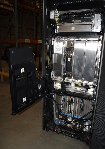
The system is in a wide, heavy rack, about 30" wide and 76" tall, and about 1500lbs, according to IBM.  This is a typical weight and size for an IBM rack of equipment (similar to older IBM S/390 and RS/6000 SP systems).  Inside the rack, starting at the top are the rack-level power supply, processor and memory cabinet (CEC), and at the bottom, the I/O card enclosure.  On a set of fold-out arms on the front side of the machine are the Service Element (SE) laptops, which are sort of a service processor - they manage loading firmware into the system, turning power on and off, configuring the hypervisor for LPARs, accessing the system consoles, and other low-level system tasks.  They manage features such as Capacity Upgrade on Demand (CUoD), Capacity Backup, limiting the hardware to what you have actually paid for, and are serial number locked to the particular machine they're connected to.

My machine is a 2086-A04 (which is common across all z890 systems), and configured as a 2086-140, with two dual-port fiber Gigabit Ethernet adapters, two dual-port 2Gb Fiberchannel/FICON adapters, and two 15-port ESCON adapters.  In addition, the SE laptops connect to the outside world using a pair of 10/100 PCMCIA ethernet adapters.  Earlier systems used Token Ring instead... I'm happy to not have to deal with Token Ring for this anymore.

Central Electronics Complex - CPU and Memory

The -140 configuration means that there's 1 CP (Central Processor), which runs at speed level 4 (on a scale of 1 to 7), which can run any z890-compatible OS.  It also has one "IFL" (Integrated Facility for Linux), which is one processor core which runs at full speed (level 7), which is microcode locked to only running Linux, and doesn't count towards the speed rating of the machine.

IBM mainframes are given a speed rating, originally in MIPS, and now in MSU, which is used to price software that runs on the mainframe.  Mine is rated 110 MIPS, and 17 MSU. By comparison, a full speed CPU is rated 366 MIPS and 56 MSU, which is the speed of my IFL.  The z890 came in 28 different speed increments (1-4 CPUS x 1-7 speed ratings) from 26 MIPS / 4 MSU to 1365 MIPS / 208 MSU, to closely match the amount of system speed you required, which helps keep your software costs down.

Processor book, with memory removed

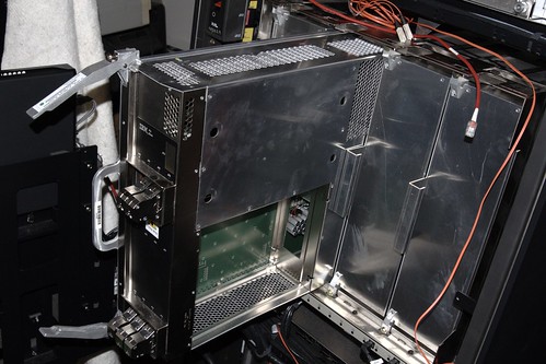
The z890 is actually nearly the same as a z990 system, with the exception that it has only one processor book (out of 4 that can fit into a one-rack z990 system), and only scales to 4 user-accessible cores (there is one additional core, called a "System Assist Processor" or SAP, which is dedicated to doing system I/O handling).  The z890 can scale up to 56 total processor cores.

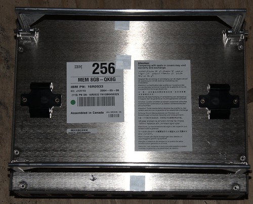
System memory module - 8GB

The system has 8GB of RAM, which is a custom module that plugs into the processor "book".  The memory is available in 8GB increments up to 32GB of ram.  The 24GB option, as there is only one RAM slot, is actually implemented as a 32GB module with 8GB "turned off" by IBM.  As you will learn by working with these systems for a bit, IBM has an annoying habit of charging you to turn on parts of the system which you already own, but haven't paid to unlock yet.

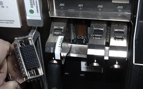
STI cables and connectors

Each processor book (which is only one for the z890) has 8 "STI" (Self-Timed Interface) links, which connect the CPU and memory to I/O adapters.  In the z890, these links run at 2GBps (16Gbps).  There are 7 that you can use in a fully configured system for I/O cards, and you can also use the remaining one (or more) to network (couple) systems together to build a system that is more redundant.  With the apporpriate hardware, you can run these coupling links (but not at the full 2GBps) up to 100km, creating as IBM calls it, a "geographically-diverse" system, which can help provide for a disaster-recovery system link.

Peripherals

Two things that I appreciate about this system compared to past systems are the ethernet on its SE (which also lets me boot the system from an FTP server on its network), and SCSI over Fiberchannel support, which lets me use standard FC raid arrays as storage for a Linux system.

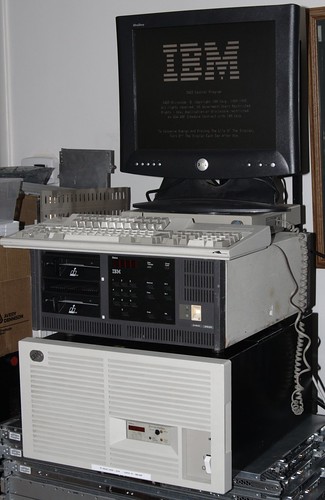
IBM 3174 Terminal Controllers and 3483 Terminal

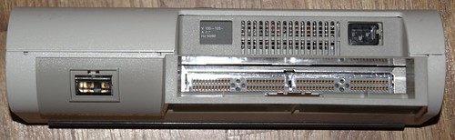
In addition, the FICON can act as a system channel (like ESCON or Bus & Tag) to appropriate peripherals, at speeds of up to about 200MBps.  It also has ESCON, which is a more traditional connection, and allows up to 17MBps connection to peripherals.  Parallel Channel (aka S/370 Channel, or Bus & Tag) peripherals can be hooked up using a protocol converter such as the IBM 9034.  This will let me connect my 3480 cartridge-style Channel-Attached tape drives, 3174-21L 3270-style terminal controllers, and eventually 3420-8 vacuum-column 9-track tape drives, to the system.

IBM 9034 Escon to Bus & Tag Converter

To Be Continued...

Future posts will document installation and setup of Debian GNU/Linux, and peripherals.

Saturday, October 9, 2010

IBM p550 at home with Debian and Infiniband


It's time for yet another blog post on getting once expensive machines running at home.

Introduction

I'm working with an IBM pSeries machine called a p550 (specifically, a model 9113-550 in IBM speak). It was built in 2004, had a list price of some 10s of kilo-bucks new, has 4 x 1.5GHz POWER5, 8GB RAM, and runs AIX up through the most recent releases of AIX 7.

It has a built-in hypervisor and what IBM calls "LPAR" support, which is a mode of virtualization which gives you "Logical PARtitions" of the memory and CPUs in the machine, with a granularity of 1/10th of a CPU. LPAR support requires a desktop machine that IBM calls an HMC, or "Hardware Management Console", which breaks out all of the logical consoles on the machine, and allows you to configure resource allocation and things like virtual ethernet switches and virtual SCSI adapters. In addition, a piece of software for the machine called VIOS or "Virtual I/O Server" is required for LPAR mode if you want to share hardware adapters (eg, ethernet, SCSI or Fiberchannel adapters) between OSes. Since I have neither of those, I am just running the machine in "bare metal" mode, with only one OS instance.

For I/O, the system has a built-in SCSI raid, gigabit ethernet, a Service Processor which controls functions like power on the machine, 5 internal hot-plug PCI-X slots, and an external link that allows for more I/O trays with disk and PCI-X cards to be added. I have installed a Mellanox Infinihost Infiniband card, to hook up to my Infiniband fabric.

Making the Service Processor work for you

In addition to the serial console port, the system has a pair of ethernet ports, which are designed to connect to a system HMC, but which also allow https-based access to the service processor menus. By default, it will try to get an address via dhcp, or you can configure it through the serial port. The Service processor requires you to log in to do anything. I believe that the default username/password combination is admin/admin. That's what we had it set to on the machines at work.

To set the IP address, you need to navigate through the menus:
5. Network Services
1. Network Configuration
1. Configure interface Eth0
Then, chose either static or dynamic, and enter information as needed.

In order to get this to work for me, I had to use Firefox, and enable an SSL option, because while it uses https, it uses a somewhat insecure method of doing SSL that is disabled by default. To enable this, put "about:config" in the address bar, and change the option "security.ssl3.rsa_null_md5" to "true". Once you do that, you can get to the web version of the service processor menus (ASPI in IBM-speak) at https://1.2.3.4 (replacing 1.2.3.4 with the IP address you set above).

One additional thing you will probably want to set up is "Serial Port Snoop" under System Service Aids -> Serial Port Snoop. Setting a "Snoop String" will all you to enter a string through the serial console to force reboot the machine if it locks up, or you do something wrong while booting, and the console isn't set to the right place.

Installing Debian

I net-booted the installer. To do this, set up the host in dhcpd.conf with an entry like this:

host p550 {
hardware ethernet 00:02:55:df:d5:dd;
fixed-address p550.blah;
next-server storage.blah;
filename "/tftpboot/debian-squeeze-ppc64-vmlinuz-chrp.initrd";
}

Boot the machine into OpenFirmware (hit "8" at the firmware "IBM IBM IBM IBM ..." screen), and net-boot from there:

0> boot net console=hvsi0

If you don't boot with the right args from openfirmware, you won't get a working console when you boot into the installer. That's where the "serial port snoop" option from the service processor comes in handy.

Once you get to the end of the installer, you will need to do some magic to get the bootloader (yaboot) installed. Hopefully, the Debian people will get some of this sorted out before the release of Squeeze. Tell the installer that you want a shell, then do this:

# mount --bind /dev /target/dev
# chroot /target
# mount -t proc proc proc
# yabootconfig
# ybin

Upgrading firmware

Debian doesn't include binary update_flash in its powerpc-utils package. Download the latest binary release in RPM format.

Convert that to an rpm with Alien (apt-get install alien if you don't have it):

# alien powerpc-utils-1.2.3-0.ppc.rpm

then

# apt-get remove powerpc-ibm-utils powerpc-utils
# dpkg -i powerpc-utils_1.2.3-1_powerpc.deb

Now, you can download a new flash image from IBM. Once you get it, use alien to convert and unpack the rpm, and do "update_flash ./tmp/fwupdate/01SF240_403_382", where 01SF240_403_382 is the flash image name from the RPM you downloaded. When you reboot the system, Linux will update the system flash just before rebooting.

Infiniband and beyond

I had some problems initially getting Infiniband set up and going. I'm using a Topspin SDR Infiniband adapter, which is basically a stock Mellanox InfiniHost . It seems that the hypervisor on the machine wasn't allocating all of the resources that the card was asking for.

After some discussion on the linuxppc-dev mailing list, it was pointed out that there are certain slots in the machine which the system calls "super slots", and which the firmware is willing to allocate more resources than a typical PCI-X card requests. This Redbook (PDF) on IBM's redbook site details Infiniband usage on pSeries systems, Section 3.4.3 indicates which slots you may install an infiniband adapter into on certain machines. On a p550, these are slots C2 and C5. I had plugged my IB adapter into slot C1, which is why I was having problems.

After getting it into the slot, it was just a matter of getting the right drivers loaded on the host OS. In order to use IP over Infiniband, you'll want the ib_ipoib module. To use RDMA and the Verbs interface, you'll want ib_umad and ib_uverbs modules to be loaded. At this point, it basically acts like a typical Linux system with Infiniband, just with more I/O bandwidth than you can get out of a typical PCI-X based system.

What next?

Setting up an HMC, and playing around with virtualization on the machine sounds like it could be a good time.

Saturday, October 2, 2010

Running an Altix 4700 supercomputer at home

Introduction

At the beginning of the year, work decomissioned the SGI Altix 4700 system that we put into production around January 2007. It sat around unused, and we had little luck finding a buyer for the system - it seems that no one is really commercially interested in running Linux on big Itanium systems anymore.

What's an Altix 4700?

Briefly, an SGI Altix 4700 is a large multi-processor SSI (single-system image) supercomputer, which uses Intel Itanium 2 (in my case, 1.6GHz, dual-core Montecito) processors, and memory on blades, which are interconnected using a "ccNUMA" architecture. This stands for "cache-coherent Non-Uniform Memory Access" - basically, a method of making large SMP-like machines by gluing processors with local memory together with a system interconnect.

With NUMA, unlike SMP, there is memory that is closer to (and thus faster from) each CPU. Like SMP, however, the system is contained in one single address space (unlike, say, a cluster which is connected using Ethernet or Infiniband). It thus runs a single OS image, and looks to the user like one large SMP system.

System Specs

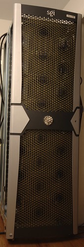
The system that I have is contained within one rack, and has 4 "bricks", each with 8 processor blades, each blade containing 2 dual-core 1.6GHz Montecito and 16GB of RAM, plus one system I/O blade with disks, PCI-X slots, Gigabit ethernet, USB, etc, and assorted NUMA routing blades and system controllers.

That totals 128 system cores, and 512GB RAM. The theoretical peak GFLOP rating of the system as configured is approx 820GF. Of course, 128 CPU and 256 DIMMs draw a bit of power...

Powering/cooling a supercomputer

Running as a full system, the computer draws 9kW of power, and requires 2 x 200-240V, 30A power circuits. That's a lot of power. I pay about $0.072/kWh, so running the system for one hour costs me about $0.65.

One issue with running a system that draws 9kW is that you get 9kW of heat output. As a coworker of mine has said, at work we run heaters, that produce computation as a side-effect. The easiest and most cost-effective solution is to open up some windows, and turn on some fans. With an outside temperature of about 60F, I can set up a few fans, open some windows, and keep the temperature inside below 80F.

It is possible to deal with this problem, to make the machine a bit more friendly and less power-hungry to run -- you can run less than a full system. By pulling out the blades that you don't want to run, you can cut down the power usage by a proportional amount. For testing purposes, I have run the system with either 1/2 or 1/8 of the blades running to reduce my power usage.

One thing I've noticed is that EFI state information (its equivalent of a PC's "CMOS" configuration memory) is stored and updated only on one system blade. So, you really want to make sure that you have blade "0" (the bottom left blade in the chassis marked "001c01") installed, or booting will become much more difficult.

Installing Debian

At work, we ran the machine with SuSE. Due to licensing issues, the fact that SuSE sucks to administer, and that I prefer to run Debian on things, I got to installing Debian. The machine runs EFI, Intel's "next-generation BIOS" that is used on Itanium (IA-64) systems, and some x86 (PC like) systems such as Apple's Intel-based systems. The boot process is pretty close to PXE booting, and Debian seems to have pretty good IA-64 support. The install went smoothly - I ended up installing "Squeeze" - the next version of Debian that will be released.

Kernel changes

In general, the Debian kernel just works. However, it only has support for up to 64 cpus (cores) built in. I downloaded the latest kernel sources from ftp.kernel.org, primed the configuration with the Debian kernel config, adjusted the max number of CPUs, recompiled, and rebooted the system into the new kernel.

I should note that being able to do a make -j 64 does a lot to speed up a kernel compile... :)

Running HPL

HPL is the standard benchmark to test the effective speed of supercomputers, and is used by the ranking on the "Top500" list at http://top500.org.

HPL is also contained within the "hpcc" benchmark collection, which is how I ran the benchmark. At first, I tried the Debian package for hpcc. I got some fairly poor results, because it doesn't use an optimized "BLAS" math library. To speed things up, I went to TACC's web site and downloaded GotoBLAS2, compiled that with the added gcc option "-mtune=itanium2", copied it to /opt, and built hpcc from its source. The instructions here are useful to build these two software packages.

What next?

The systems' CPUs aren't all that fast compared to modern CPUs. For example, the rating in Gigaflops of all 128 cores is about 4 x the rating of a 3.2GHz IBM/Sony Cell BE CPU. One place that the system does have an advantage, though, is its 512GB of DDR2 memory. Someone could easily plug an Infiniband, 10 Gigabit Ethernet, or Fiberchannel card into the machine, and turn it into a pretty snappy solid-state drive, accessible over iSCSI, FCoE, Infiniband SDP, or straight FC.

The next item that I'm going to work on, is getting some FPGA blades from another Altix system working in the 4700, and test out writing code to use the FPGAs to speed up compute intensive tasks. An example of what FPGAs are typically used for is to search a genomics database for a particular DNA sequence. Basically, any algorithm that is applied to a stream of data can be a good candidate for putting into an FPGA.