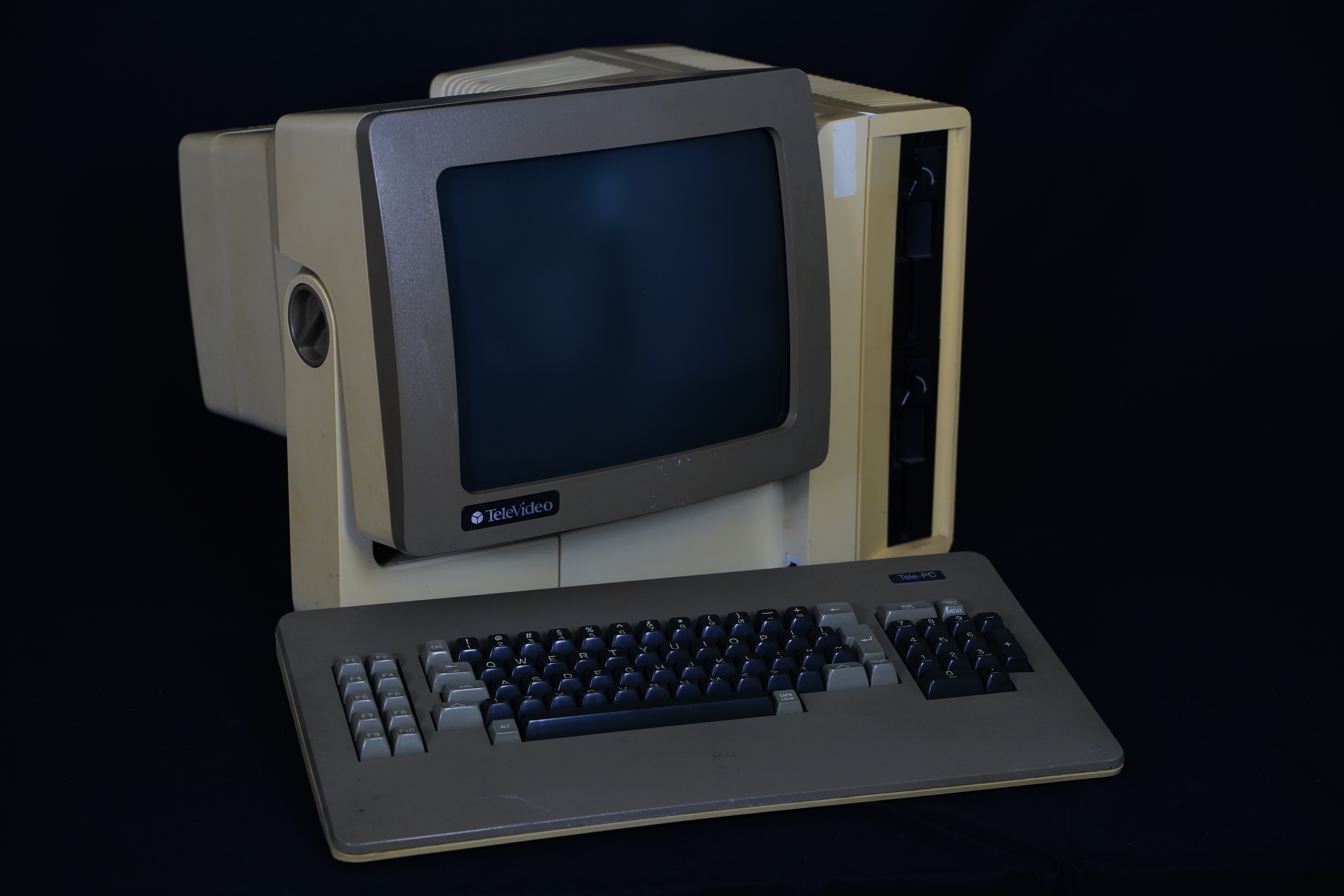
TeleVideo TS-1605 PC/XT Clone
The TeleVideo TS-1605 is one of their first PC clone systems, and unlike the earlier TS-1603, it includes expansion capabilities using an ISA card slot, and optional ISA expansion chassis.
I ended up picking up one of eBay with a few known faults, hoping that I could fix them. The two errors were obvious in the eBay listing, a 201 and 601 error. Based on IBM's standard numbering this meant there probably was a memory fault and a floppy disk fault of some sort.
The front has a modular 6-pin coiled cable coming out of it to plug a keyboard into. This appears to be a mostly IBM PC/XT compatible keyboard but powered using 12V instead of 5V. I haven't quite figured out if it can be made to be compatible with a PC/XT keyboard, and my initial attempts didn't work out with supply 12V power the keyboard and connecting it to an IBM 5160 PC/XT.
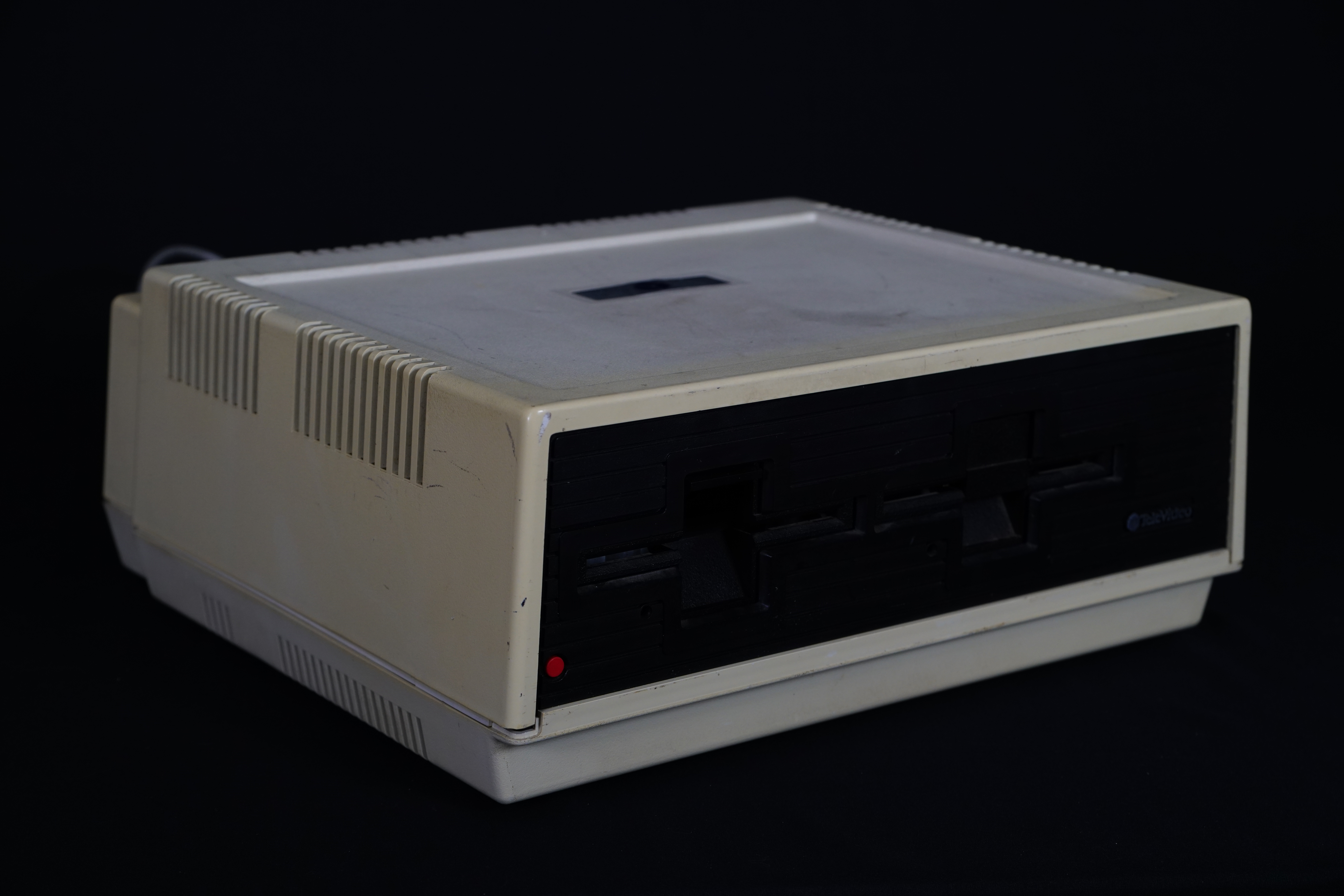
The front also shows to vertically stacked 360KB (DSDD, 48tpi) TEAC FD-55B floppy drives, which are the same as TeleVideo used in the TS-803 CP/M system.
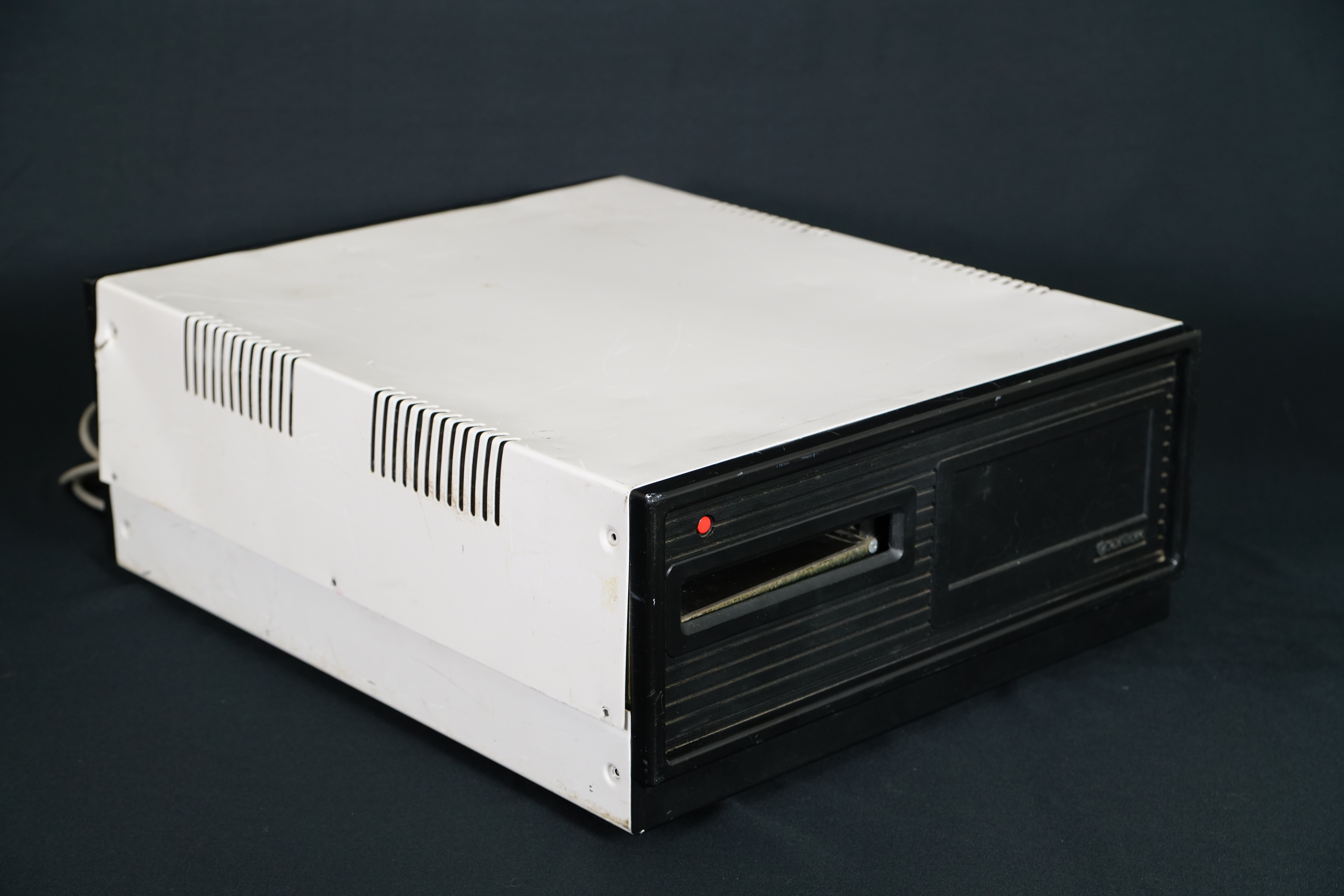
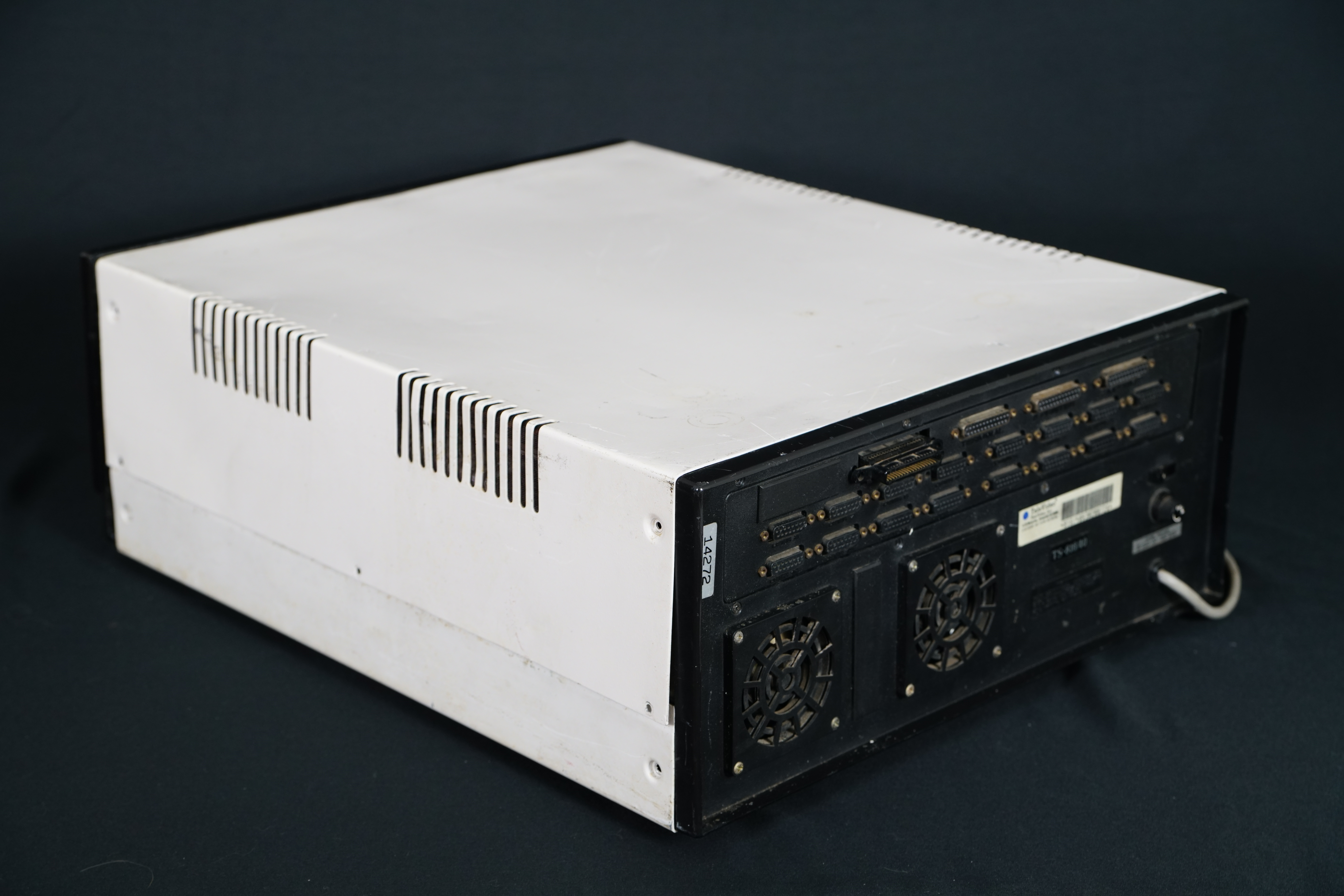
The back of the system shows some integrated peripherals:


Inside there was a 256K ram expansion card installed into the card slot. The slot itself is mounted on a cable that plugs into a 64 pin header on the board, making it easy to remove to connect something external to.

Removing that shows off some features on the system board:


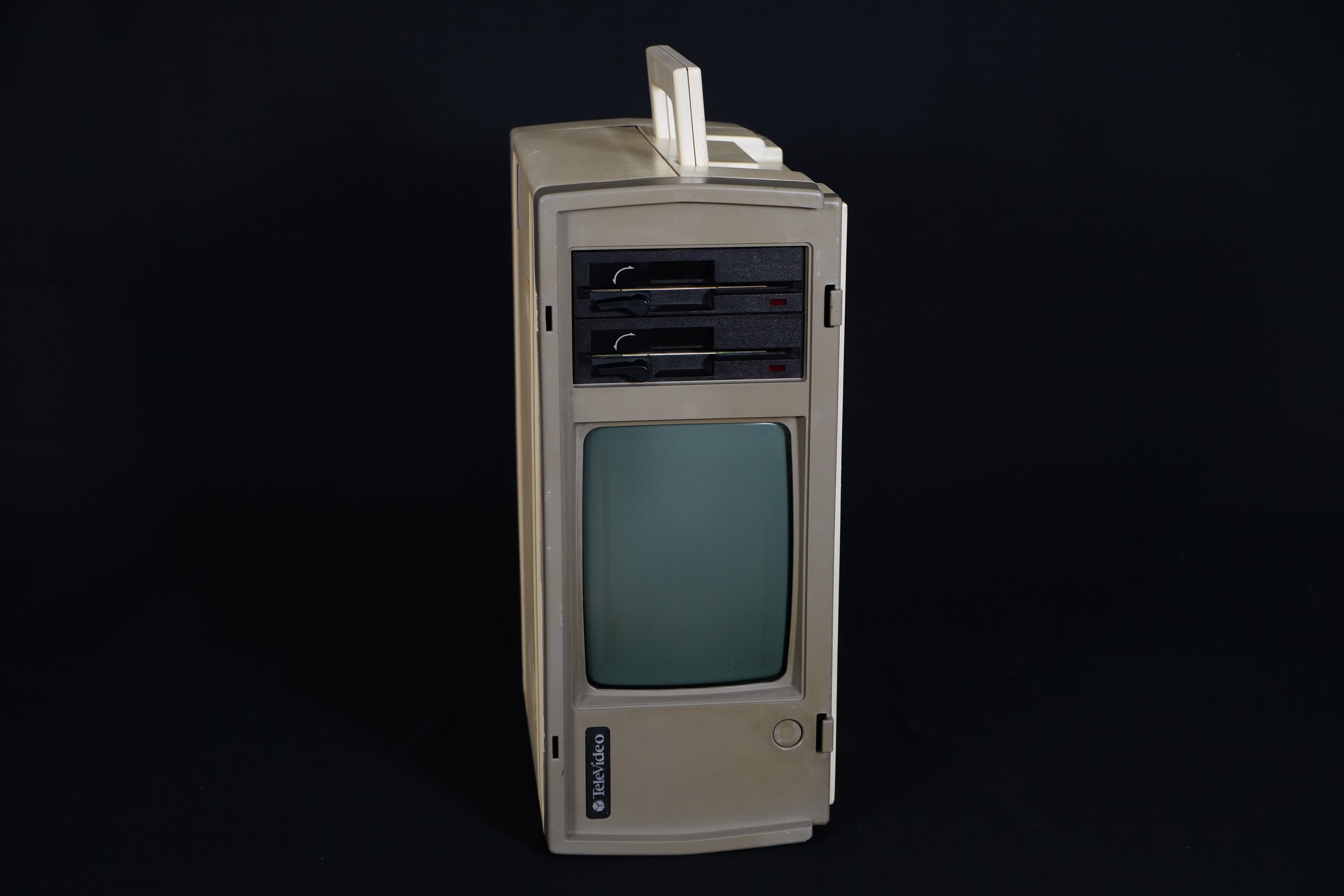
Outside appearances
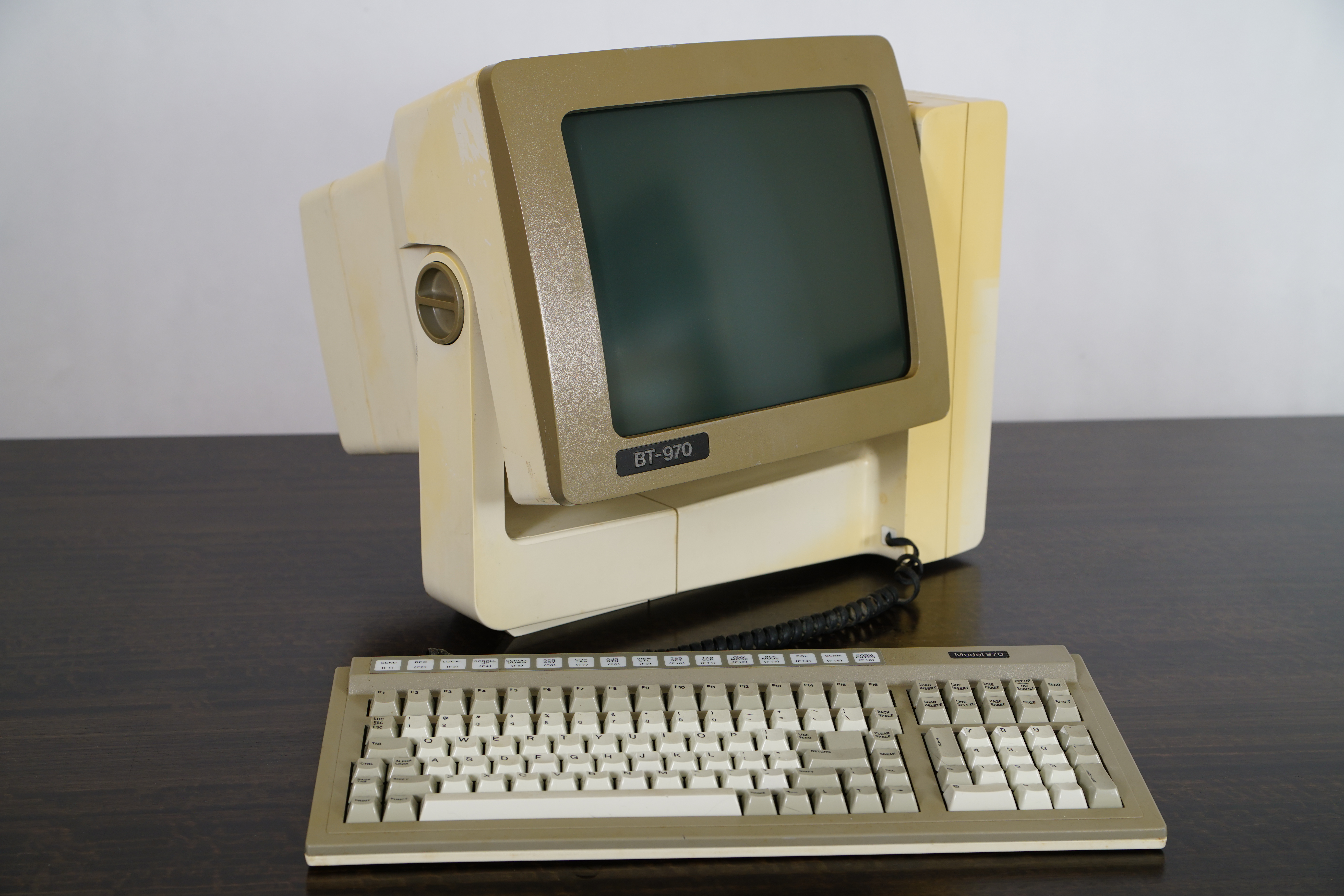
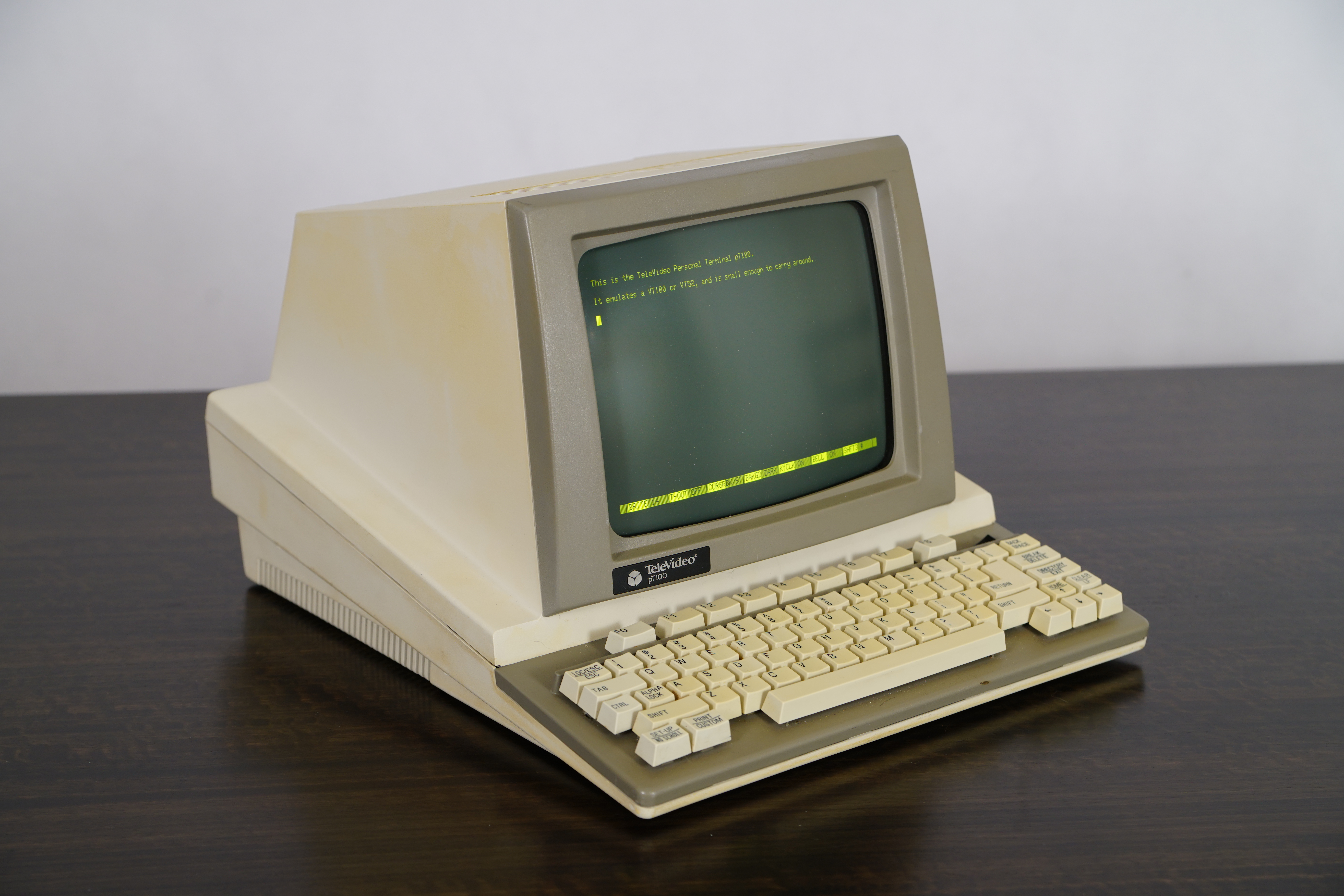
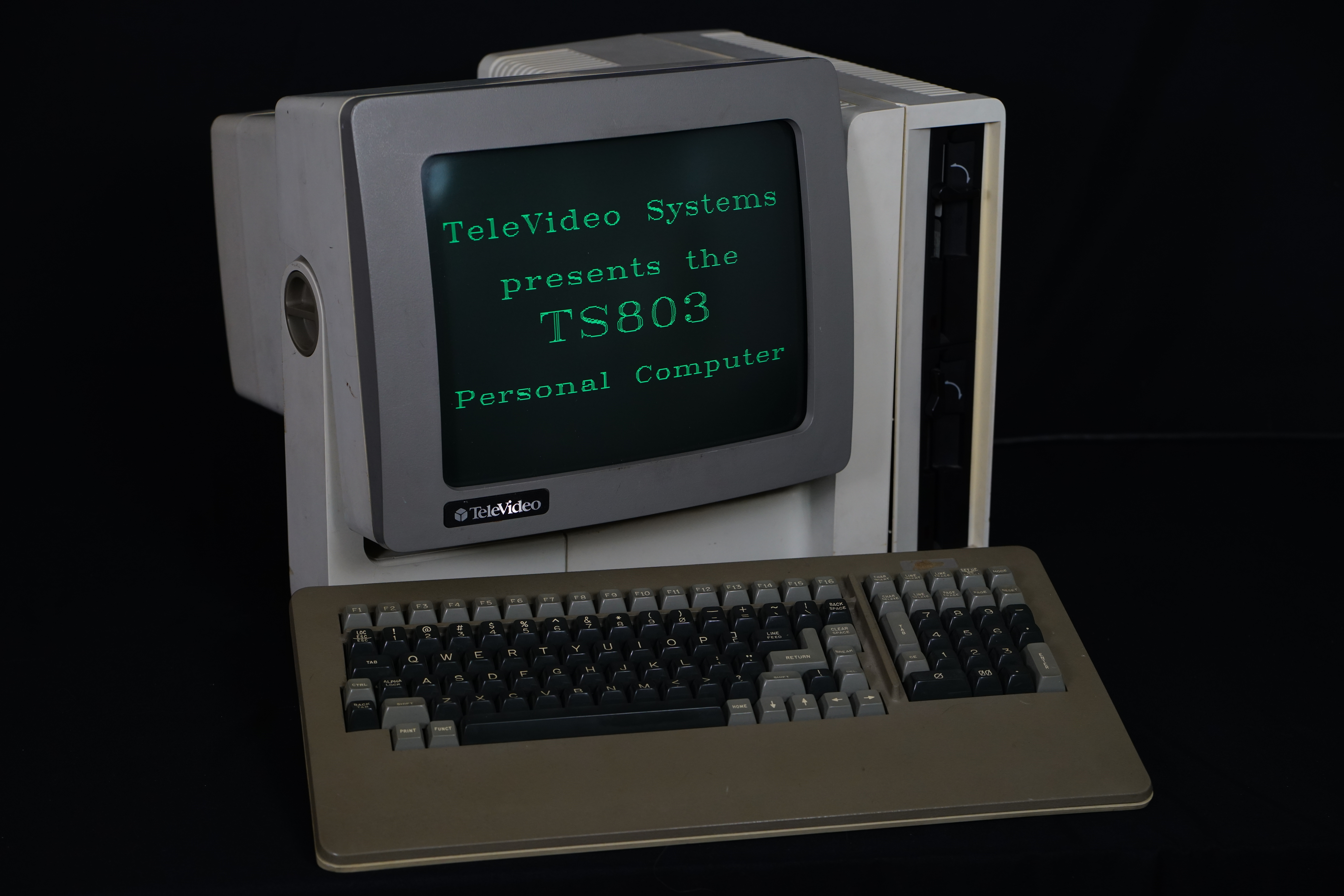
This system, based on the 970 terminal and TS-803 before it, has a nice 14" green phosphor tilting screen, and a base that swivels nicely if it's placed on a hard surface.The front has a modular 6-pin coiled cable coming out of it to plug a keyboard into. This appears to be a mostly IBM PC/XT compatible keyboard but powered using 12V instead of 5V. I haven't quite figured out if it can be made to be compatible with a PC/XT keyboard, and my initial attempts didn't work out with supply 12V power the keyboard and connecting it to an IBM 5160 PC/XT.
The front also shows to vertically stacked 360KB (DSDD, 48tpi) TEAC FD-55B floppy drives, which are the same as TeleVideo used in the TS-803 CP/M system.
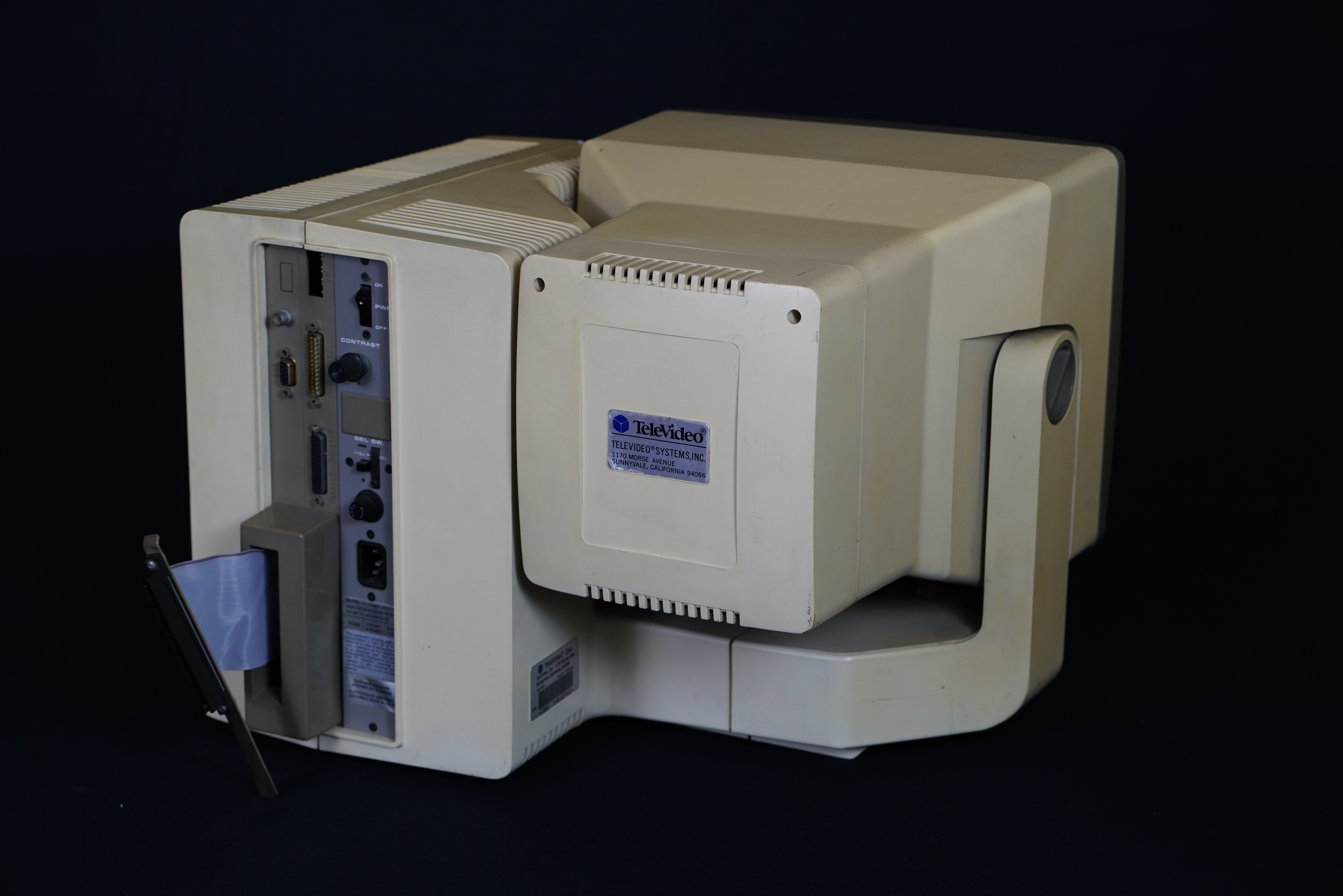
- RCA jack and DE-9F RGBI output, compatible with an IBM CGA monitor.
- DB-25M RS-232 serial port from an 8250 UART
- DB-25F IBM-compatible Centronics interface parallel printer port
- DIP switches for setting, easily accessible from the back of the case
- A built-in ISA expansion slot, for connecting one card, or an expansion chassis, which I pulled through the expansion slot hole to make it easier to connect cards.
Disassembling the system

System with side cover removed
The system is fairly easy to get the cover off with only 3 screws at the bottom of the right side holding it on. I figured that before I would power the system up, I should pull it apart, and test out the power supply outputs, and check that everything physically looked OK.

RAM card close-up

System board close-up with 8088 CPU / 8087 socket and connectors for floppy drive, hard drive controller, and 64-pin ISA slot header.
Removing that shows off some features on the system board:
- Intel 8088 CPU
- Slot for 8087 math coprocessor
- 4 memory banks and an option MUX chip to allow upgrading the stock 128K of ram to 256K (4 banks of 4164) or 512K (2 banks of 41256) -- the system only allows 4 banks of 256K RAMs
- 32K of static ram in 51400 chips for video memory
- TeleVideo gate array and ROM chips for the CGA-compatible video card and system BIOS
- An NEC 765 and FDC9229B floppy controller and data separator
- 34-pin IBM-compatible floppy drive connector
- An onboard 6-pin modular jack for the keyboard cable
- 40-pin WD1000 compatible hard drive interface, which is the same as used on various Z80 systems, including the TS-802H, 803H, 806, and 816.
Debugging memory

System board RAM, 4 banks of 8 chips, and BIOS EPROM
First, I tried to find and eliminate the memory fault. I started by pulling out the memory expansion card, which didn't help at all. All of the onboard memory was socketed, so I went through and tried to find which chips were bad. The system still tried to boot with a reduced amount of memory and the "201" memory error, so I hoped to boot up DOS and used DEBUG to find the bad memory.
This didn't go quite as well as I planned. The floppy drives didn't work either, so I was trying to boot off an XT-IDE card. However, as soon as it displayed the boot menu, the system would freeze, and not display any input. I first figured this was due to the memory issue, but it turns out that it wasn't. Fortunately, I had another 8-bit IDE card which I was able to use, and boot off an SD card in an IDE to SD adapter. It's a "Centos, Inc. CI-1020", as far as I can tell not related to RedHat.
Once I got booting sorted out, I was able to boot up MS-DOS 5.0, run DEBUG, and poke around memory. I discovered that a section of RAM had one bit that was stuck on. I didn't have schematics, so I went through and replaced memory chips one bank at a time until the error went away. Once I did that, I put back memory chips one at a time until the error re-appeared. That helped isolate the one bad 4164 chip. Fortunately, I have a stack of spare 4164 from Quadboard and AST Six Pack expansion boards.
Debugging floppy drives

Floppy controller and video memory/chips
The next problem I went to diagnose was the "601" disk error. Booting off of a floppy disk didn't work, and the drive didn't respond from within DOS either. However, the drive light and motor did turn on, so at least some parts were working.
At this point, I had found a schematic in the technical manual for the machine on eBay. So, I could see that the drive select/motor lines were driven by a latch chip on the motherboard. The rest of the drive controller was integrated, and the way that it was all integrated, it would have been a major effort to replace the onboard controller with an ISA card. So, I pulled out my oscilloscope and started looking at things.
First, I looked at the data line from the drives to the controller. With a disk in the drive, and the system trying to use the disk (I had to do this from within DOS since the BIOS didn't even try to boot off of the failed controller) I saw pulses that looked like flux transitions on the disk. So far so good - the drives were probably OK.
The system uses an NEC D765 floppy controller, and an FDC9229B data separator, to convert the data stream into clock and data pulses for the controller. So, one of these two chips were likely the problem. Hooking the scope up to pins on the NEC chip, it looks like it was receiving its chip select line, clock, read/write, etc, ok. However, I noticed that the chip wasn't responding to commands, and the data line from the FDC9229B was stuck low.
I wasn't sure at this point if it was the D765 or FDC9229B. However, both were available on eBay for reasonable prices, so I got both. A few days later, I had received both of them and continued with debugging. Replacing the D765 didn't change anything until I had also replaced the FDC9229B. With it working correctly, I put back the original D765, and that worked as well. So I had narrowed it down to the FDC9229B and pitched the old one.
It was fortunate that both chips were socketed, so it was easy to swap them out. Otherwise, the repair process would have taken much longer (I would have had to replace both of them, as it's difficult to desolder chips from boards without damaging one of them). And in the end, they would have ended up with sockets anyways.
Expanding I/O

ISA expansion
The system came with only one ISA slot but was also offered with an expansion chassis for additional card slots. I thought I'd try an easy solution to get more slots. On eBay, I was able to find an ISA riser card with multiple slots, which had a normal ISA card-edge connector on it. The one I found was called a "Generic CTK-303" like these on eBay.
I was able to pull the ISA slot cable out through the hole at the back of the case and plug it in. Note that it's a 16-bit riser card, where the computer has the original IBM 5150 PC style 8-bit slots. This doesn't really matter, as long as I don't try to use any cards where the 16-bit "extension" slot gets in the way. Few cards had that problem, such as the IBM original CGA card. However, with the built-in CGA compatible video, I wasn't going to be using a CGA card in this either.
I found a collection of cards to plug in, including a 3com 3c503 Ethernet card, 8-bit IDE card, IBM 3270 emulator card, RAM expansion, and serial port card, and booted the system back up. Everything seemed functional (I didn't test every card, but I didn't see any signs that I had overloaded the bus).
The Future!
Going forward, there's a few things I'd like to work on. I'd like to use the system with the IBM 3270 card and IBM's PCOMM as a 3270 terminal, mostly because it looks cool. I'd also like to stick the ISA riser card into an external chassis with a separate power supply, and cable back to the host. Since the connection is just a standard 64-pin header connector on the system, this should be relatively easy. It'd also help getting the memory up to 640K or so. I have purchased the memory MUX chip and have a stack of 41256's, which would let me at least increase the memory on the system board to 512K.


